Tags and keywords
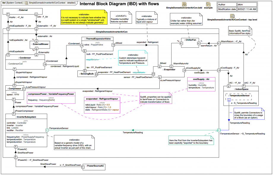
SimpleDomesticInverterAirCon - with internal details showing - within the «system context» block SimpleDomesticInverterAirConContext, along with usages of a block External representing the outdoor environment and a usage of an air-conditioned IndoorSpace:A word on some naming and display options
Both the names and the Types of Ports external to :SimpleDomesticInverterAirCon have been shown here. By contrast, to reduce clutter, the Types of most Ports internal to :SimpleDomesticInverterAirCon are not displayed explicitly in this diagram. To some extent this modelling option has been used:
Note that sometimes it's sufficient to instead only show the Port type. The gist is that it's seldom necessary to show both the name and the Type of every Port and it can make Internal Block Diagrams harder to read.
Note, by contrast, that every usage of a Block is anonymous (which is sufficient for this trail because the usages are not being exported to, for example, Modelica or Simulink):
The temperature control loop and the refrigerant cycle as ItemFlows
There's a lot to discuss here, and plenty to learn about SysML modelling options, so settle in as we work our way through the entire flow cycle.
Some of the ItemFlows have an itemProperty applied. This is a nice way of demonstrating the transformations of stuff that is flowing, such as the refrigerant.
On a SysML modelling matter, it would be nice to be able to show more information about each itemProperty on an ItemFlow on a Connector:
In the meantime, one can always just (slightly redundantly and verbosely) show the Property symbol for each itemProperty on the IBD and expose their :values compartments. (SysMLv2 is going to have some more powerful ways of carrying and displaying such information.)
We'll start our journey with the sensed temperature and our simple control loop. Recall first this recommendation:
So there's an explicit input Port iTemperatureSensor delegating to a similar Port on :InverterSubsystem, which accepts the sensor input as the temperatureGot value and uses it to determine the frequencyAim of the power driving the :Compressor, on the basis of the difference between the temperatureGot and the temperatureAim. This ultimately changes the rpm of the :Compressor.
The (hopefully fully) evaporated:RefrigerantVapour at low pressure is transformed in the :Compressor to super hot compresssed:RefrigerantVapour, which enters the :Condensor.
An :ExternalBlower draws in cooler external air which is used to help cool and condense the refrigerant. The hotExpelledAir:Air is ejected to the :External environment.
The condensed:RefrigerantLiquid then passes to the :ThermalExpansionValue, which is in this model an old mechanical style TXV/TEV with a :PoppetValue, which has a diaphragm that is equalised with the pressure of a :SensingBulb (typically placed near the top of the :Evaporator and connected via a metal capillary to the head of the thermal expansion value so its charge pushes on the diaphragm). The temperature of the :SensingBulb equalises with the temperature at the top of the :Evaporator to measure any "superheat". This is indicated by a custom stereotype keyword «equilibrium».
If you want to learn how a basic mechanical thermal expansion valve works visit these links (after completing this SysML trail of course):
You'll recall from a previous slide that the Port types for the pressure equalisation and temperature equalisation were modelled SysPhS-style, but no actual calculations are done in this trail, it's just assumed that «equilibrium» is reached quickly, as indicated by a custom stereotype keyword.
The evaporation of the expanded:Refrigerant (a tuned mixture of liquid and vapour) results in cooling of the warmReturn:Air drawn using a :ChillerFan, and coolSupply:Air is injected to the :IndoorSpace, cooling the room as required to hopefully approach the temperatureAim.
So that's a physical representation of the flows and transformations; let's now see how in SysML we can also represent the refrigerant part of that cycle as a StateMachine driven by Activities.


