
There are lots of things I love about MagicDraw® UML (aka Magic Software Architect), the MagicDraw SysML Plugin, and Magic Cyber-Systems Engineer® (Cameo Systems Modeler®), it is my main professional tool of trade. This long-standing flaw is definitely not one of them.In MagicDraw® UML (aka Magic Software Architect) or Magic Cyber-Systems Engineer ® (Cameo Systems Modeler®), if you select an "Object Node" (which has an abstract metaclass) from the Activity Diagram menu items and place it on the diagram it will create a «centralBuffer» node symbol, which is just plain wrong.
If you use the smart manipulator from an Action symbol to create an ObjectFlow and don't connect it up to another Action or an existing Pin on another Action, it creates an OutputPin, an ObjectFlow, and a «centralBuffer» node symbol, which is also just plain wrong.
At least in version 19SP3, if you have an "ObjectFlow symbol" (there is in fact no such thing for elided Pin notation, there are only object node arrow symbols, see below) to a «centralBuffer» node directly from an Action that has a Pin it warns you that 'All pins that are created for this action must be displayed in the diagrams'. But that warning is itself also just plain wrong.
The notation as described in the UML specification is probably difficult to implement in a tool, but it is in fact quite clear (if somewhat strange):
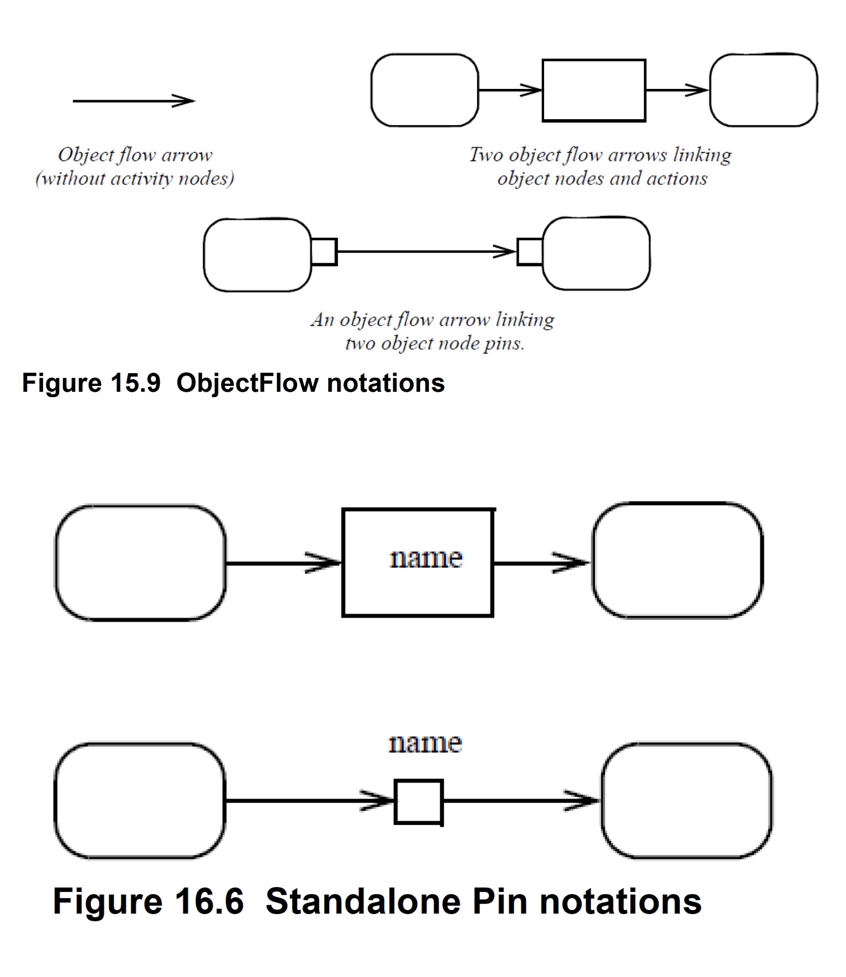
The referenced Figure 15.9 ObjectFlow notations is reproduced here for convenience.Note how it says (Webel's emphasis in bold) 'two object flow arrows denote a single object flow edge'. An object flow arrow is a notation symbol, it DOES NOT ALWAYS CORRESPOND ONE-TO-ONE TO A SINGLE ELEMENT IN THE MODEL!
Not convinced yet? More of the same from the spec:
The referenced Figure 16.6 Standalone Pin notations is reproduced here for convenience.And what the tool is doing contradicts this:
[If you go from an InputPin to a compatible OutputPin, an object flow arrow corresponds one-to-one to an ObjectFlow edge in the model; MagicDraw/Cameo does get that case right.]