TIP: SysMLv1: Cameo: Can't see the Item Flow Manager icons in the smart manipulators for an ObjectFlow in an Activity Diagram with swimlanes? Try setting Item Flow Creation Mode to 'Between Part Types' instead of 'Direct' under your Project settings!
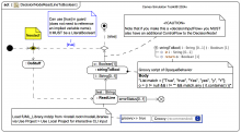
SysMLv1: A basic ControlFlow, ObjectFlow, and DecisionNode loop driven by fUML ReadLine CLI String input with conversion to Boolean for LiteralBoolean guard [with mini video] Gallery Tutorial TRAIL: SysMLv1/UML: Cameo Simulation Toolkit® (Magic Model Analyst®): Some basics for beginners and some more advanced cases [with mini videos] Section Slide kind SysML Activity Diagram UML Activity Diagram
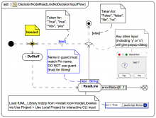
SysMLv1: A basic ControlFlow, ObjectFlow, and DecisionNode loop driven by fUML ReadLine CLI String input [with mini video] Gallery Tutorial TRAIL: SysMLv1/UML: Cameo Simulation Toolkit® (Magic Model Analyst®): Some basics for beginners and some more advanced cases [with mini videos] Section Slide kind SysML Activity Diagram UML Activity Diagram
SysMLv1: A basic ControlFlow and DecisionNode loop with implied variable popup dialog [with mini video] Gallery Tutorial TRAIL: SysMLv1/UML: Cameo Simulation Toolkit® (Magic Model Analyst®): Some basics for beginners and some more advanced cases [with mini videos] Section Slide kind SysML Activity Diagram UML Activity Diagram
TRAIL: SysMLv1/UML: Cameo Simulation Toolkit® (Magic Model Analyst®): Some basics for beginners and some more advanced cases [with mini videos] Jump to first slide SysMLv1: A basic ControlFlow and DecisionNode loop with implied variable popup dialog [with mini video] Sections
TIP: SysMLv1/UML: Cameo Simulation Toolkit: HOWTO convert an fUML ReadLine CLI String to a Boolean for cleaner DecisionNode tests against a LiteralBoolean [true] guard.
TIP/GOTCHA: SysMLv1/fUML: Cameo Simulation Toolkit: If you have a ControlFlow loop with a DecisionNode test you MUST have a MergeNode for the continuation path ControlFlow (typically entered also from an InitialNode or other loop starting point).
TIP/GOTCHA: SysMLv1/UML: Cameo Simulation Toolkit: If you use a «decisionInputFlow» to a DecisionNode you MUST also have a ControlFlow to the DecisionNode; if you don't use an explicit «decisionInputFlow» you don't need the "extra" ControlFlow
Webel: Psy/MPsy: Psychrometrics for Mathematica: '$HC' in a function name indicates pure sensible heating or cooling (with no change in water vapour content). Such functions may also be used in the pure sensible portion of a 2-step treatment.
SysML/UML: MagicDraw/Cameo: GOTCHA: Connecting a typed OutputPin to an untyped (UNSPECIFIED) InputPin with an ObjectFlow changes the type of the InputPin
Webel: SysML4Mathematica: Convention: A '$E' in a function name indicates that all parameters (arguments and return) are Mathematica '_' expressions. However, when representing such functions as Activities they may end up getting strongly typed in tools!
[FIXED in v2022Refresh1]: BUG: MagicDraw/Cameo: 19SP3/v2022xGolden: Activity Diagrams: Pin display mode 'Position of Labels' does not stick, label positions in Diagrams have sometimes moved after re-opening a project [and "FIX"] ARCHIVAL (2022): This content is now considered historical only!
MagicDraw/Cameo 19SP3/v2022xGolden: [FIXED in v2022xRefresh1]: Activity Diagrams: Pin display mode 'Position of Labels' does not work correctly for 'Name And Type Labels Inside', only shows the Name inside (not the Label) [and WORKAROUND] ARCHIVAL (2022): This content is now considered historical only!
A DecisionNode accepts tokens on its primary incoming edge and offers them to all its outgoing edges. However, each token offered on the primary incoming edge shall traverse at most one outgoing edge. Tokens are not duplicated. Source Unified Modeling Language 2.5.1
When an Action in an Activity completes execution, object tokens for output data placed on its OutputPins may be offered on any outgoing ObjectFlows from those Pins ... In addition, control tokens shall be offered on any outgoing ControlFlows ... Source Unified Modeling Language 2.5.1
If the outgoing edge of a MergeNode is a ControlFlow, then all incoming edges must be ControlFlows, and, if the outgoing edge is an ObjectFlow, then all incoming edges must be ObjectFlows. Source Unified Modeling Language 2.5.1
If the incoming edge is a ControlFlow, then all outgoing edges shall be ControlFlows and, if the incoming edge is an ObjectFlow, then all outgoing edges shall be ObjectFlows. Source Unified Modeling Language 2.5.1
Unlike ControlFlows, ObjectFlows also provide additional support for multicast/receive, token selection from ObjectNodes and transformation of tokens Source Unified Modeling Language 2.5.1
An ObjectFlow is an ActivityEdge that can have object tokens passing along it. ObjectFlows model the flow of values between ObjectNodes. Source Unified Modeling Language 2.5.1
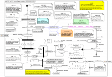
uml101 - Activity Diagram - notation - REFERENCE CARD This content has been marked as discussing an ADVANCED topic! Gallery Tutorial TRAIL: Webel's ultimate guide to Systems Modeling Language (v1) with MagicDraw/Cameo Section 01:04: UML Behavior: Activities quick start Slide kind UML Activity Diagram
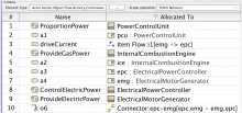
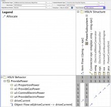
Allocation table in the MagicDraw/Cameo tool Gallery Tutorial TRAIL: Webel's ultimate guide to Systems Modeling Language (v1) with MagicDraw/Cameo Section 15:01: The Allocate relationship and functional analysis Slide kind MagicDraw/Cameo: allocation matrix MagicDraw/Cameo: relationship dependency matrix matrix
Allocation matrix in the MagicDraw/Cameo tool Gallery Tutorial TRAIL: Webel's ultimate guide to Systems Modeling Language (v1) with MagicDraw/Cameo Section 15:01: The Allocate relationship and functional analysis Slide kind MagicDraw/Cameo: allocation matrix MagicDraw/Cameo: relationship dependency matrix matrix
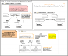
Figure 15-7: Example of flow allocation from ObjectNode to FlowProperty Gallery Tutorial TRAIL: The SysML-1.6 Hybrid SUV sample and specification diagrams in MagicDraw/Cameo (with annotations) [UNDERGOING UPDATE to SysML1.7] Section Section: SysML-1.6 specification diagrams: 15 Allocations Slide kind hybrid diagram SysML Activity Diagram SysML Internal Block Diagram (IBD)
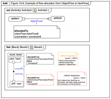
Figure 15-6: Example of flow allocation from ObjectFlow to ItemFlow Gallery Tutorial TRAIL: The SysML-1.6 Hybrid SUV sample and specification diagrams in MagicDraw/Cameo (with annotations) [UNDERGOING UPDATE to SysML1.7] Section Section: SysML-1.6 specification diagrams: 15 Allocations Slide kind hybrid diagram SysML Activity Diagram SysML Internal Block Diagram (IBD)
SysML-1.6: Figure 15-5 does not show 'flow allocation of ObjectFlow .. alternatively to an ItemFlow', Figure 15-6 does.
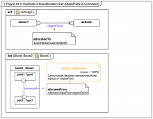
Figure 15-5 shows flow allocation of [an] ObjectFlow to a Connector, or alternatively to an ItemFlow. Source OMG Systems Modeling Language (SysML) 1.6
Figure 15-5: Example of flow allocation from ObjectFlow to Connector Gallery Tutorial TRAIL: The SysML-1.6 Hybrid SUV sample and specification diagrams in MagicDraw/Cameo (with annotations) [UNDERGOING UPDATE to SysML1.7] Section Section: SysML-1.6 specification diagrams: 15 Allocations Slide kind hybrid diagram SysML Activity Diagram SysML Internal Block Diagram (IBD)
The edges coming out of the decision node indicate the probability of each branch being taken. Source OMG Systems Modeling Language (SysML) 1.6
The decision node and guards determine if the brake pressure is greater than zero, and flow is directed to value specification actions that output an enabling or disabling control value from the activity. Source OMG Systems Modeling Language (SysML) 1.6
Claim: The ControlValue input to Monitor Traction without a Pin is invalid in 'Figure 11-10: Continuous system example 1' and multiple issues with ControlOperator
An ObjectFlow is an ActivityEdge that is traversed by object tokens that may hold values. Object flows also support multicast/receive, token selection from object nodes, and transformation of tokens. Source Unified Modeling Language 2.5.1
no_executable_nodes ObjectFlows may not have ExecutableNodes at either end. Source Unified Modeling Language 2.5.1
SysML-1.6: The allocation from ObjectNode 'driveCurrent' in Figure D.38 to itemFlow 'i1' on the Connector in Figure D.39 does not appear in the allocation table Figure D.40; Instead there is an allocation from an ObjectFlow 'o6' to the Connector 'epc-emg'
MagicDraw/Cameo: 19SP3: Callout of allocatedFrom on Connector vs ObjectFlow shows «decisionInputFlow» not «objectFlow» keyword
Multiple arrows coming out of a standalone Pin rectangle is an optional notation for multiple edges coming out of an OutputPin. Source Unified Modeling Language 2.5.1
The standalone Pin in the notation maps to an OutputPin and an InputPin and one ObjectFlow edge between them in the underlying model. This form should be avoided if the Pins are not of the same type. Source Unified Modeling Language 2.5.1
The situation in which the OutputPin of one Action is connected to the InputPin of the same name in another Action via an ObjectFlow may be shown by the optional notations of Figure 16.6. Source Unified Modeling Language 2.5.1
An object flow is notated by an arrowed line. In Figure 15.9, upper right, the two object flow arrows denote a single object flow edge between two pins in the underlying model, as shown in the lower middle of the figure. Source Unified Modeling Language 2.5.1
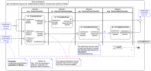
Figure D.38 - Detailed Behavior Model for “Provide Power” {EXPLICIT PINS} Gallery Tutorial TRAIL: The SysML-1.6 Hybrid SUV sample and specification diagrams in MagicDraw/Cameo (with annotations) [UNDERGOING UPDATE to SysML1.7] Section Section: SysML-1.6: HSUV sample Slide kind SysML Activity Diagram
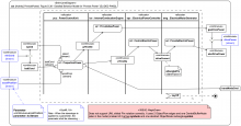
Note that the incoming and outgoing object flows for the ProvidePower activity have been decomposed. This was done to distinguish the flow of electrically generated mechanical power and gas generated mechanical power, and to provide further insight ... Source OMG Systems Modeling Language (SysML) 1.6
Figure D.38 - Detailed Behavior Model for “Provide Power” {ELIDED PINS} Gallery Tutorial TRAIL: The SysML-1.6 Hybrid SUV sample and specification diagrams in MagicDraw/Cameo (with annotations) [UNDERGOING UPDATE to SysML1.7] Section Section: SysML-1.6: HSUV sample Slide kind SysML Activity Diagram
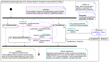
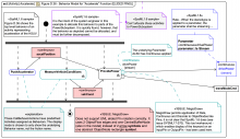
Figure D.37 defines a decomposition of the activities and objectFlows from the activity diagram in Figure D.36. Source OMG Systems Modeling Language (SysML) 1.6
Figure D.36 - Behavior Model for “Accelerate” Function (Activity Diagram) {EXPLICIT PINS} Gallery Tutorial TRAIL: The SysML-1.6 Hybrid SUV sample and specification diagrams in MagicDraw/Cameo (with annotations) [UNDERGOING UPDATE to SysML1.7] Section Section: SysML-1.6: HSUV sample Slide kind SysML Activity Diagram
MagicDraw/Cameo: ERROR: Incorrectly uses 2 ObjectFlow edges and a CentralBufferNode in place of "elided Pin notation" instead of an abstract ObjectNode symbol and 2 arrow symbols (that are supposed to represent together 2 Pins and 1 ObjectFlow edge)
Figure D.36 - Behavior Model for “Accelerate” Function (Activity Diagram) {ELIDED PINS} Gallery Tutorial TRAIL: The SysML-1.6 Hybrid SUV sample and specification diagrams in MagicDraw/Cameo (with annotations) [UNDERGOING UPDATE to SysML1.7] Section Section: SysML-1.6: HSUV sample Slide kind SysML Activity Diagram
If the primary incoming edge of a DecisionNode is a ControlFlow, then all outgoing edges shall be ControlFlows and, if the primary incoming edge is an ObjectFlow, then all outgoing edges shall be ObjectFlows. Source Unified Modeling Language 2.5.1
15.3.3.6 Decision Nodes - A DecisionNode is a ControlNode that chooses between outgoing flows. Source Unified Modeling Language 2.5.1
two_input_parameters If the DecisionNode has a decisionInputFlow and a second incoming ObjectFlow, then any decisionInput has two in Parameters ... Source Unified Modeling Language 2.5.1
decisionInputFlow : ObjectFlow [0..1] ... An additional ActivityEdge incoming to the DecisionNode that provides a decision input value for the guards ValueSpecifications on ActivityEdges outgoing from the DecisionNode. Source Unified Modeling Language 2.5.1
Held object tokens are offered to outgoing flows according to the general ordering rules for ObjectNodes. When an offer for a token is accepted by a downstream object node, that token is removed from the CentralBufferNode and moved to the accepting ... Source Unified Modeling Language 2.5.1
15.4.3.3 Central Buffer Nodes - A CentralBufferNode acts as a buffer between incoming ObjectFlows and outgoing ObjectFlows. It accepts all object tokens offered to it on all incoming flows, which are then held by the node. Source Unified Modeling Language 2.5.1