
Tags and keywords
The Modelica By Example target code is:
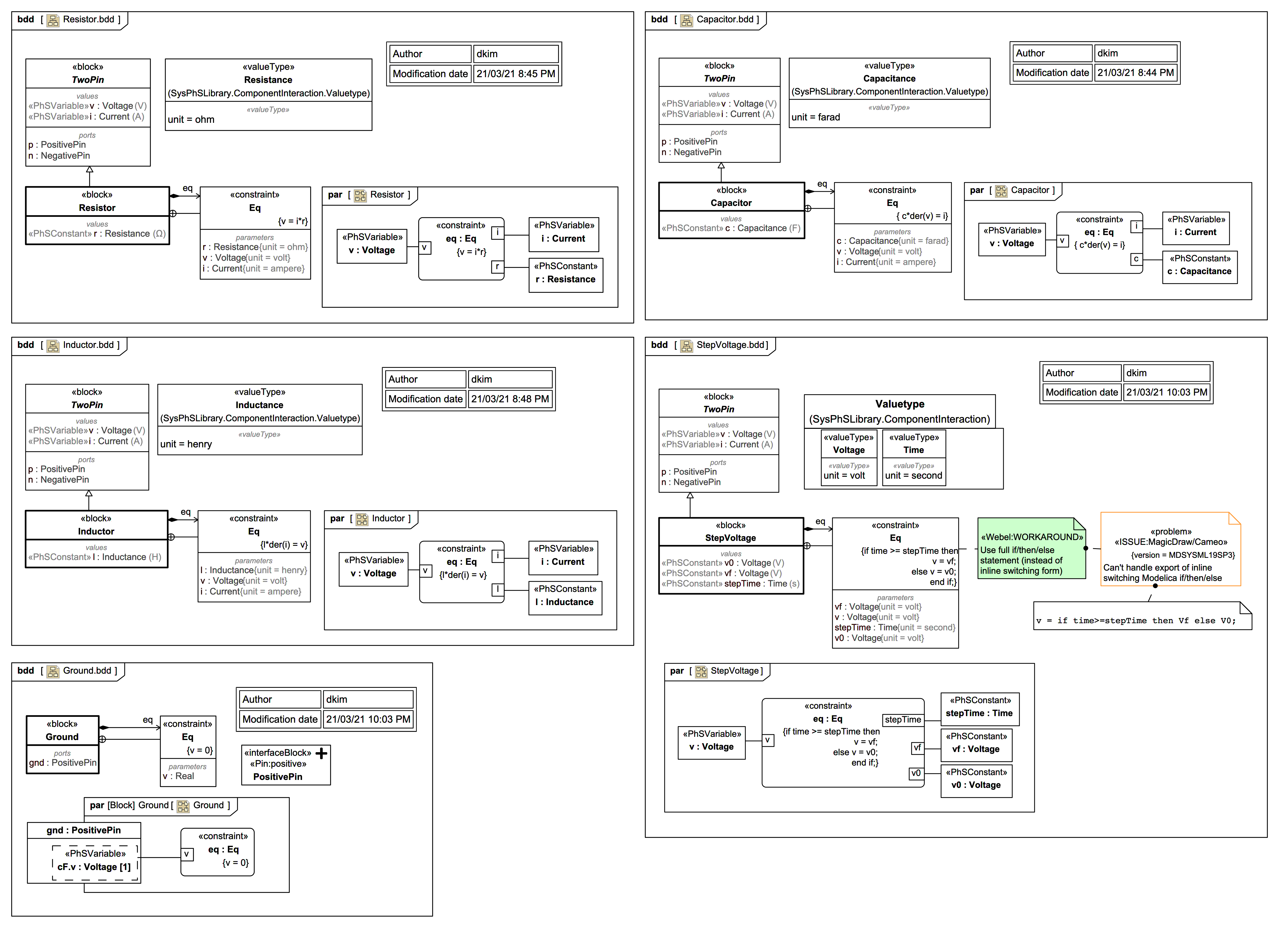
within ModelicaByExample.Components.Electrical.DryApproach;
model Resistor "A DRY resistor model"
  parameter Modelica.SIunits.Resistance R;
  extends TwoPin;
equation
  v = i*R "Ohm's law";
end Resistor;
within ModelicaByExample.Components.Electrical.DryApproach;
model Capacitor "A DRY capacitor model"
  parameter Modelica.SIunits.Capacitance C;
  extends TwoPin;
equation
  C*der(v) = i;
end Capacitor;
within ModelicaByExample.Components.Electrical.DryApproach;
model Inductor "A DRY inductor model"
  parameter Modelica.SIunits.Inductance L;
  extends TwoPin;
equation
  L*der(i) = v;
end Inductor;
within ModelicaByExample.Components.Electrical.DryApproach;
model StepVoltage "A DRY step voltage source"
  parameter Modelica.SIunits.Voltage V0;
  parameter Modelica.SIunits.Voltage Vf;
  parameter Modelica.SIunits.Time stepTime;
  extends TwoPin;
equation
  v = if time>=stepTime then Vf else V0;
end StepVoltage;
within ModelicaByExample.Components.Electrical.DryApproach;
model Ground "Electrical ground"
  Modelica.Electrical.Analog.Interfaces.PositivePin ground "Ground pin"
    annotation ...
equation
  ground.v = 0;
end Ground;
Except for Ground they all reuse TwoPin from the previous diagram.
This SysML/SysPhS trail version uses slightly different and more concise naming.
The exported Modelica code (exported as usages to be shown in the next slide) is:
  model StepVoltage
    extends TwoPin;
    parameter Voltage v0;
    parameter Voltage vf;
    parameter Time stepTime;
  equation
    if time>=stepTime then
v=vf;
else
v=v0;
end if;
  end StepVoltage;

  model Inductor
    extends TwoPin;
    parameter Inductance l;
  equation
    l*der(i)=v;
  end Inductor;

  model Capacitor
    extends TwoPin;
    parameter Capacitance c;
  equation
    c*der(v)=i;
  end Capacitor;

  model Resistor
    extends TwoPin;
    parameter Resistance r;
  equation
    v=i*r;
  end Resistor;

  model Ground
    PositivePin gnd;
  equation
    gnd.v=0;
  end Ground;

  connector PositivePin
    extends ChargeFlowElement;
  end PositivePin;

  connector NegativePin
    extends ChargeFlowElement;
  end NegativePin;

  model TwoPin
    PositivePin p;
    NegativePin n;
    Voltage v;
    Current i;
  equation
    v=p.v-n.v;
    i=p.i;
    p.i+n.i=0;
  end TwoPin;

  connector ChargeFlowElement
    flow Current i;
    Voltage v;
  end ChargeFlowElement;

  type Voltage=Real(unit="V");
  type Time=Real(unit="s");
  type Inductance=Real(unit="H");
  type Capacitance=Real(unit="F");
  type Resistance=Real(unit="Ω");
  type Current=Real(unit="A");
The Modelica By Example choice of PositivePin in Ground is not ideal, but it's reproduced in this SysML/SysPhS trail version anyway. If you look at the Modelica library version it has a more neutral basic pin:
model Ground "Ground node"
  Interfaces.Pin p;
equation
  p.v = 0;
end Ground;
connector Pin "Pin of an electrical component"
  SI.ElectricPotential v "Potential at the pin";
  flow SI.Current i "Current flowing into the pin";
end Pin;