
Tags and keywords
The Modelica By Example target code is:
within ModelicaByExample.Components.Electrical.Examples;
model SwitchedRLC "Recreation of the switched RLC circuit"
  DryApproach.StepVoltage Vs(V0=0, Vf=24, stepTime=0.5)
    annotation ...
  DryApproach.Inductor inductor(L=1, i(fixed=true, start=0))
    annotation ...
  DryApproach.Capacitor capacitor(C=1e-3, v(fixed=true, start=0))
    annotation ...
  DryApproach.Resistor resistor(R=100) annotation ...
  DryApproach.Ground ground
    annotation ...
equation
  connect(inductor.n, resistor.n) annotation ...
  connect(capacitor.n, inductor.n) annotation ...
  connect(inductor.p, Vs.p) annotation ...
  connect(capacitor.p, ground.ground) annotation ...
  connect(resistor.p, ground.ground) annotation ...
  connect(Vs.n, ground.ground) annotation ...
end SwitchedRLC;
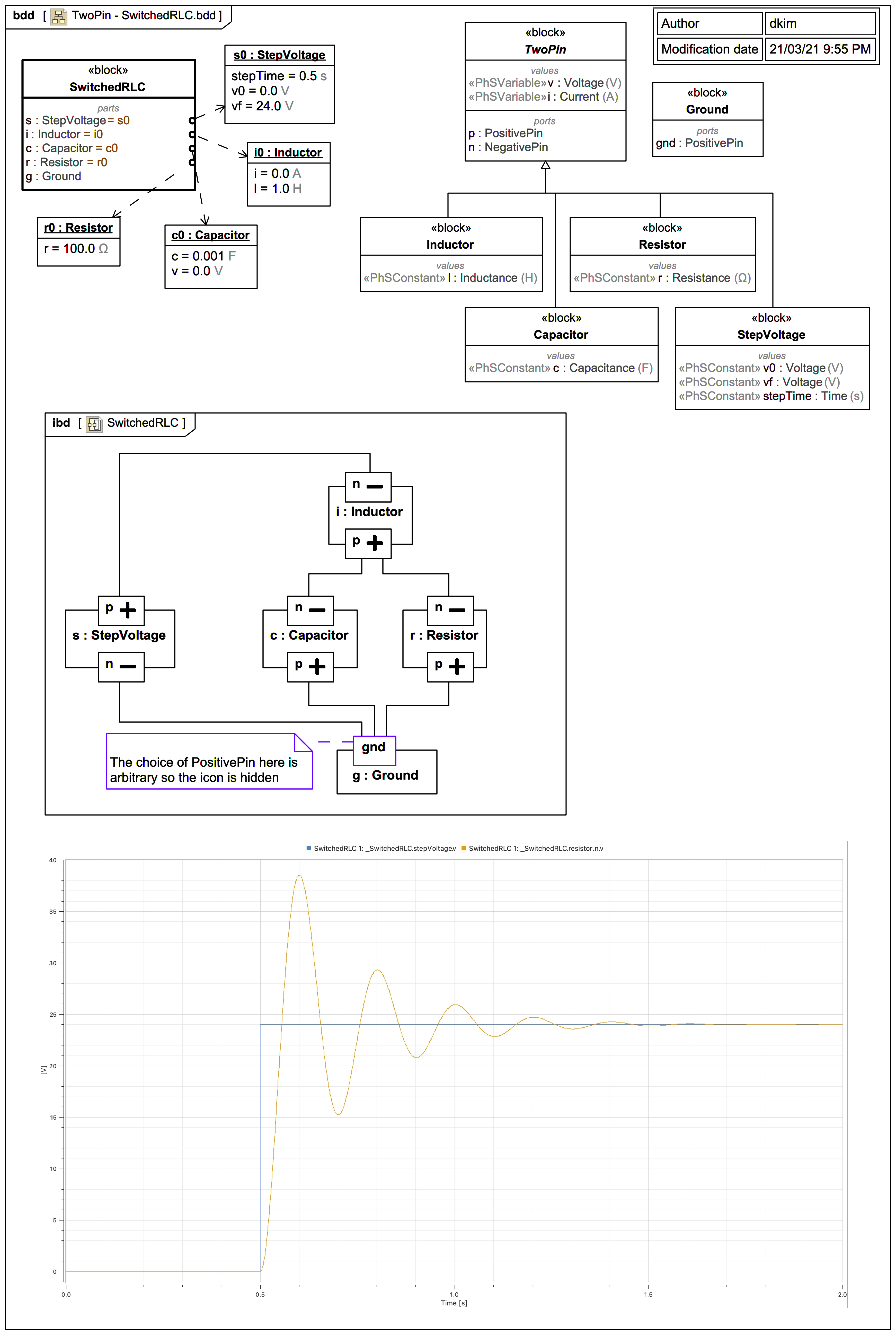
This reuses one of each of the components from the previous diagram to build the following circuit:

This page contains content quoted, copied, or adapted for educational purposes from the Modelica By Example tutorials for educational purposes. The original © copyright is retained by Dr. Michael M. Tiller.
This SysML/SysPhS trail version uses slightly different and more concise naming.
The complete exported Modelica code for block SwitchedRLC is:
model SwitchedRLC
  SwitchedRLC _SwitchedRLC;
  model SwitchedRLC
    StepVoltage s(v0.start=0.0,v0.fixed=true,vf.start=24.0,vf.fixed=true,stepTime.start=0.5,stepTime.fixed=true);
    Inductor i(l.start=1.0,l.fixed=true,i.start=0.0,i.fixed=true);
    Capacitor c(c.start=0.001,c.fixed=true,v.start=0.0,v.fixed=true);
    Resistor r(r.start=100.0,r.fixed=true);
    Ground g;
  equation
    connect(s.p,i.n);
    connect(i.p,r.n);
    connect(i.p,c.n);
    connect(r.p,g.gnd);
    connect(c.p,g.gnd);
    connect(g.gnd,s.n);
  end SwitchedRLC;
  model StepVoltage
    extends TwoPin;
    parameter Voltage v0;
    parameter Voltage vf;
    parameter Time stepTime;
  equation
    if time>=stepTime then
v=vf;
else
v=v0;
end if;
  end StepVoltage;
  model Inductor
    extends TwoPin;
    parameter Inductance l;
  equation
    l*der(i)=v;
  end Inductor;
  model Capacitor
    extends TwoPin;
    parameter Capacitance c;
  equation
    c*der(v)=i;
  end Capacitor;
  model Resistor
    extends TwoPin;
    parameter Resistance r;
  equation
    v=i*r;
  end Resistor;
  model Ground
    PositivePin gnd;
  equation
    gnd.v=0;
  end Ground;
  connector PositivePin
    extends ChargeFlowElement;
  end PositivePin;
  connector NegativePin
    extends ChargeFlowElement;
  end NegativePin;
  model TwoPin
    PositivePin p;
    NegativePin n;
    Voltage v;
    Current i;
  equation
    v=p.v-n.v;
    i=p.i;
    p.i+n.i=0;
  end TwoPin;
  connector ChargeFlowElement
    flow Current i;
    Voltage v;
  end ChargeFlowElement;
  type Voltage=Real(unit="V");
  type Time=Real(unit="s");
  type Inductance=Real(unit="H");
  type Capacitance=Real(unit="F");
  type Resistance=Real(unit="Ω");
  type Current=Real(unit="A");
end SwitchedRLC;
The not-so-ideal choice of PositivePin by Modelica By Example Ground is disguised here by hiding the custom stereotype icon in the Internal Block Diagram (IBD).
The plot gives the same result as the non-component version from much earlier in this trail.