
Tags and keywords
within ModelicaByExample.Connectors;
package Graphics
  connector PositivePin
     Modelica.SIunits.Voltage v;
     flow Modelica.SIunits.Current i;
    annotation ...
  end PositivePin;

  connector NegativePin
     Modelica.SIunits.Voltage v;
     flow Modelica.SIunits.Current i;
    annotation ...
  end NegativePin;
end Graphics;
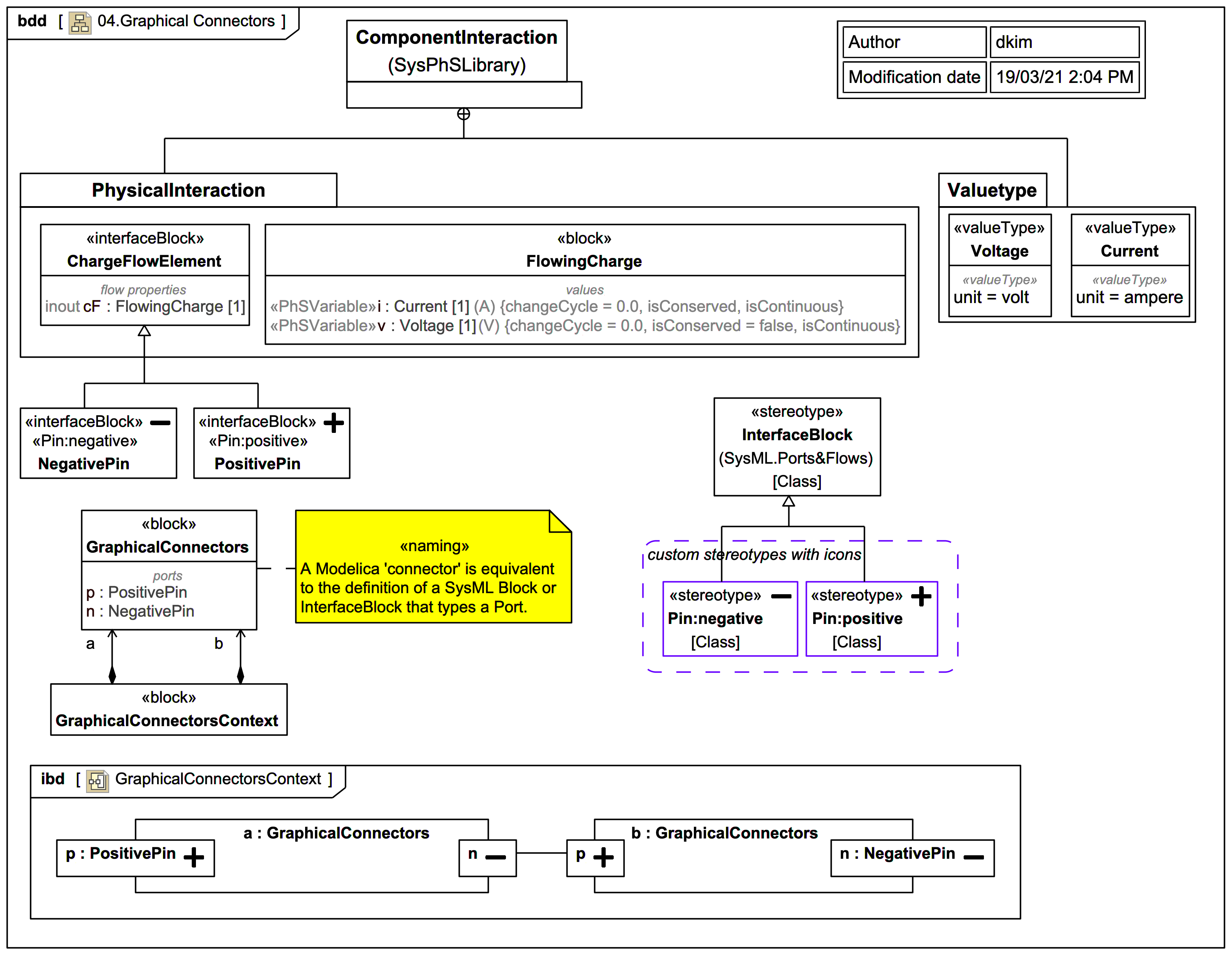
Part of the point of Modelica example is to show how one can create distinctive icons for each Modelica connector type using annotations. One can achieve something similar using custom stereotype icons.
In this SysPhS trail version the interface block ChargeFlowElement from the SysPhSLibrary is reused by inheriting into NegativePin and PositivePin, with corresponding custom stereotypes applied. A block GraphicalConnectors has Ports types by each.
The block GraphicalConnectorsContext has 2 usages of GraphicalConnectors with one example SysML Connector (a Modelica connect), and exports via SysPhS to Modelica as:
model GraphicalConnectorsContext
  GraphicalConnectorsContext _GraphicalConnectorsContext;
  model GraphicalConnectorsContext
    GraphicalConnectors a;
    GraphicalConnectors b;
  equation
    connect(a.n,b.p);
  end GraphicalConnectorsContext;
  model GraphicalConnectors
    PositivePin p;
    NegativePin n;
  end GraphicalConnectors;
  connector NegativePin
    extends ChargeFlowElement;
  end NegativePin;
  connector PositivePin
    extends ChargeFlowElement;
  end PositivePin;
  connector ChargeFlowElement
    flow Current i;
    Voltage v;
  end ChargeFlowElement;
  type Current=Real(unit="A");
  type Voltage=Real(unit="V");
end GraphicalConnectorsContext;
In the Internal Block Diagram (IBD) in MagicDraw/Cameo the (not so well named) Enable Parts Compartment feature has been used on the Ports, along with the option to only show the custom Stereotype icons (not the Sterotypes name). The Type of the Port is only verbosely shown on the 2 non-connected Ports.