Tags and keywords
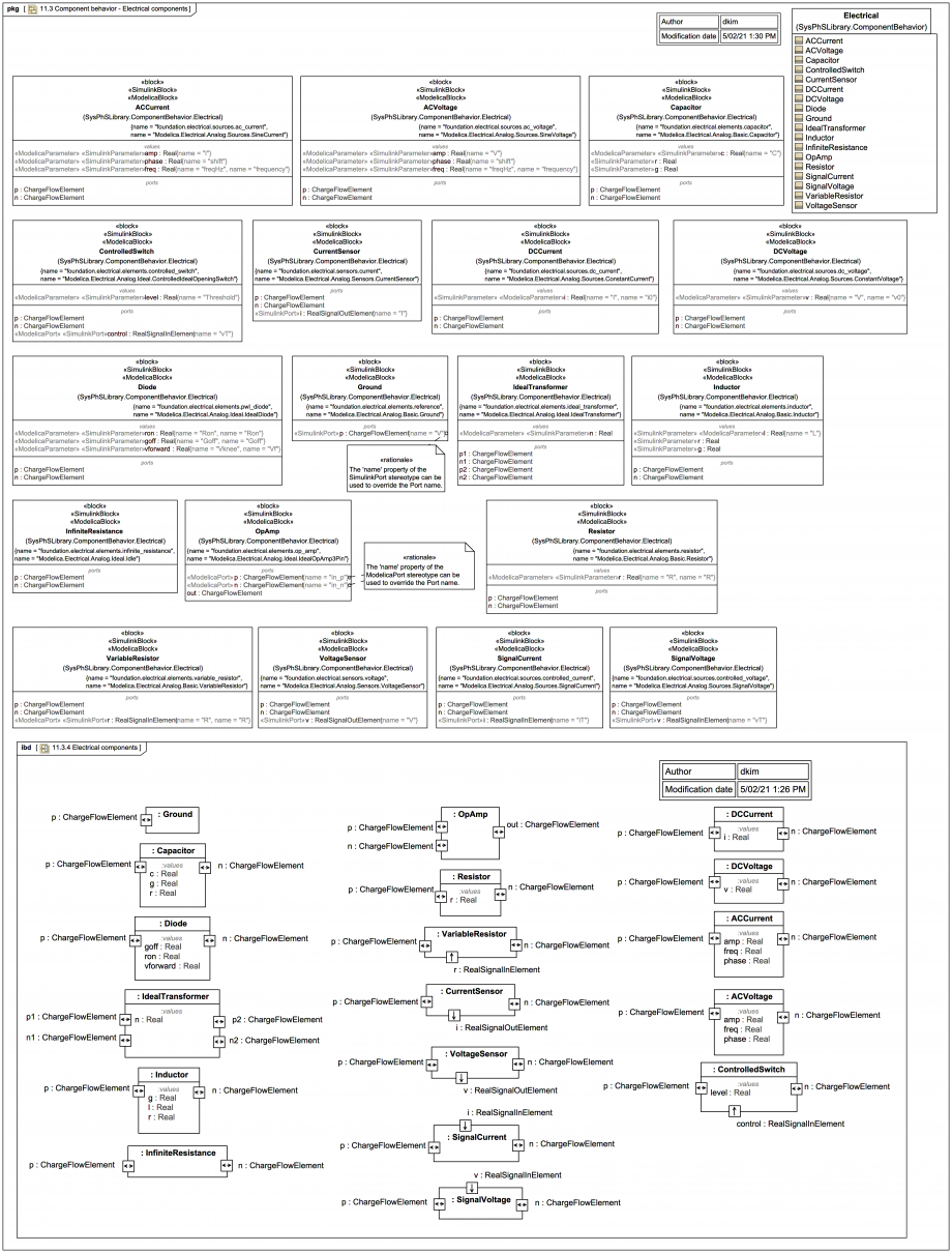
The following image combines a Block Definition Diagram (BDD) representation of MagicDraw/Cameo SysPhSLibrary components vs the SysPhS-1.1 spec table 11.3.4 Electrical components and an unwired representation of them in a Internal Block Diagram (IBD):
Beware that:
Note how some of the Port names have been re-mapped using the 'name' tagged value of «ModelicaPort» or «SimulinkPort».
There are a couple of subtleties when dealing with the electrical components.
Note how some of the Port names have been re-mapped using the 'name' tagged value of «ModelicaPort» or «SimulinkPort».
There are a couple of subtleties when dealing with the electrical components.
The Port 'p' on the SysPhS Electrical.Ground block is 'inout'. It maps to a Modelica Pin, where:
Modelica.Electrical.Analog.Interfaces.Ground is:
connector Pin "Pin of an electrical component"
  SI.ElectricPotential v "Potential at the pin";
  flow SI.Current i "Current flowing into the pin";
end Pin;
So current i flowing back out of the Ground is negative.
Where Modelica.Electrical.Analog.Interfaces.OnePort is extended by many basic analog components such as Modelica.Electrical.Analog.Basic.Resistor.
It's worth noting that use of the term Connector in UML/SysML is very different from that of the connector keyword in Modelica, as explained under: Concerning definitions: "a connector end" vs "a connector between 2 ends" vs "connection" vs "connect" in various technologies.


