
Tags and keywords
This Block Definition Diagram (BDD) shows definitions of most elements in the mini system:
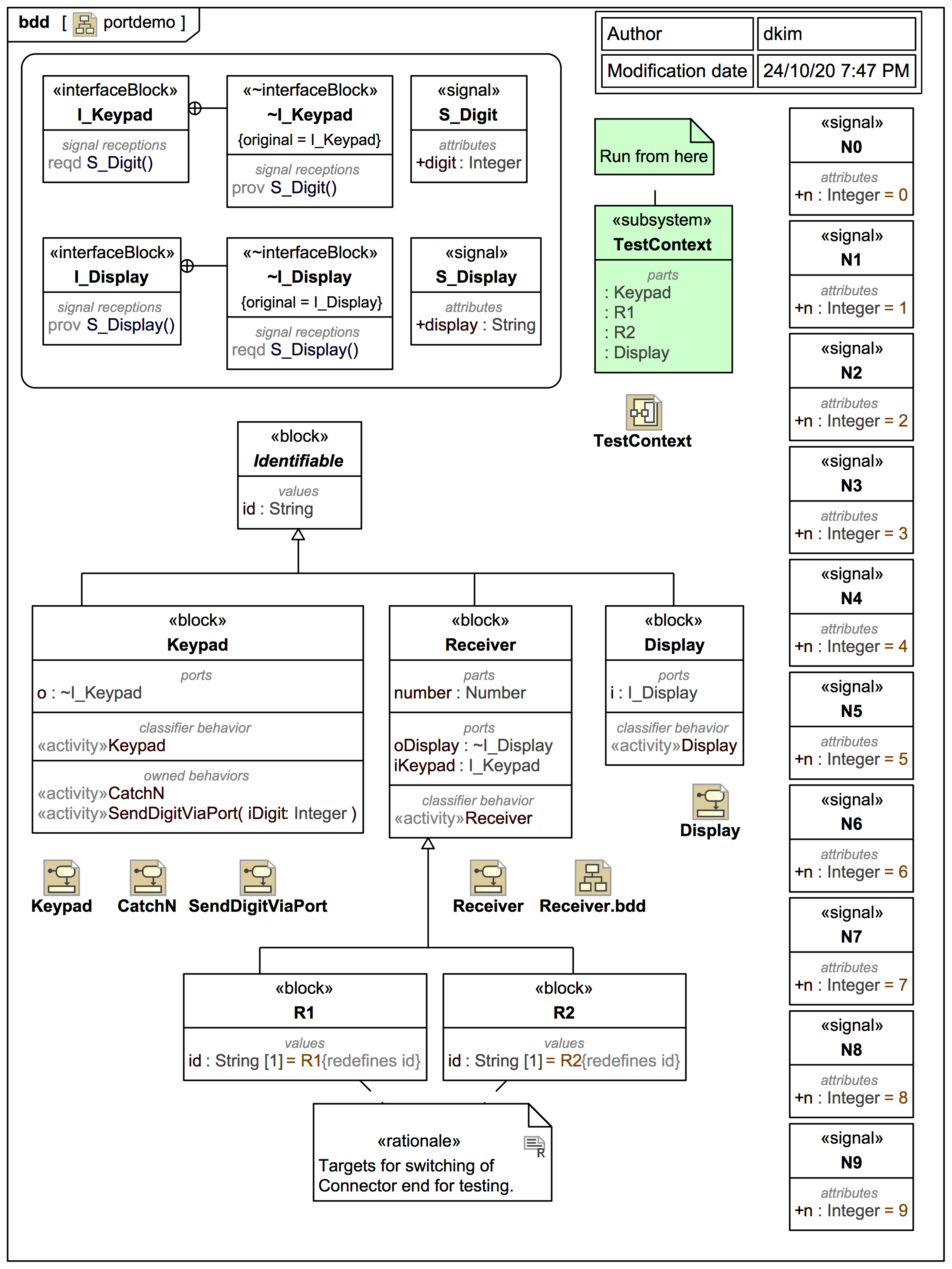
Let's start with the interface block contracts and a minor warning:
You should nevertheless use consistent SysML-style, type-based conjugation as shown. For example, the InterfaceBlock I_Keypad defines a provided reception of Signal S_Digit (which carries a digit:Integer). The block Keypad has an output port o:~I_Keypad, where the conjugated ~InterfaceBlock ~I_Keypad formally has a required Signal S_Digit.
The Receiver has sub-blocks R1 and R2 that can identify themselves via redefined id. It has an input Port iKeypad:I_Keypad and an output Port oDisplay:I_Display.
The Display is relatively trivial, with an input Port i:I_Display.
The Signals N0, N1 etc. each carry a corresponding Integer will act as simple keypad "dialer" buttons in Magic Model Analyst® (Cameo Simulation Toolkit®)
.