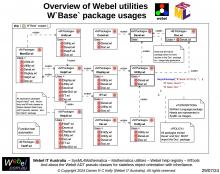
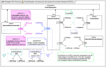
Webel: SysML4Mathematica: A SysML/UML Usage (keyword «uses») is used to indicate a Wolfram Package Needs import, where an «M:Package» is a specialisation of Block (not a SysML/UML Package) and denotes a Wolfram Language Package.
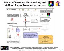
Webel W`Base` vs Git repository and Wolfram Player Pro encoded version Gallery Tutorial [TECHNICAL SLIDE TRAIL] The Webel libraries for Wolfram Mathematica: With SysMLv1 models. Section SECTION: A brief look at the Webel W`Base` utilities for Mathematica
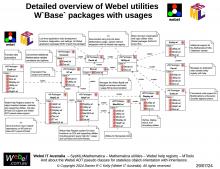
Detailed overview of Webel utilities W`Base` packages with usages Gallery Tutorial [TECHNICAL SLIDE TRAIL] The Webel libraries for Wolfram Mathematica: With SysMLv1 models. Section SECTION: A brief look at the Webel W`Base` utilities for Mathematica
Overview of Webel utilities W`Base` packages as SysML Usages Gallery Tutorial [TECHNICAL SLIDE TRAIL] The Webel libraries for Wolfram Mathematica: With SysMLv1 models. Section SECTION: A brief look at the Webel W`Base` utilities for Mathematica
Webel: SysML4Mathematica: TIP: Representing Mathematica Paclets and their inter-dependencies as SysML Packages modelled in SysML Package Diagrams can really help you organise your Wolfram Language code on complex projects!
SysML-1.6: The provided/required Interfaces indicated in the spec version of D.19 for 'connector c1 in Figure D.19.' are not defined on the corresponding Block in Figure D.20 (known issue)
MagicDraw: Has an additional tool-specific notation and feature sometimes called "ball-and-socket dependency wiring" for use with provided and required Interfaces in Class Diagrams and some other definition-level diagrams.
Required/Provided Interface notation: Ball-and-Socket "dependency wiring" [tool specific] Gallery Tutorial TRAIL: Webel's ultimate guide to Systems Modeling Language (v1) with MagicDraw/Cameo Section 01:02: UML 101 for model-based systems engineering with SysML Slide kind UML Class Diagram
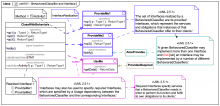
Required Interfaces specify services that a BehavioredClassifier needs in order to perform its function and fulfill its own obligations to its clients. Source Unified Modeling Language 2.5.1
Interfaces may also be used to specify required Interfaces, which are specified by a Usage dependency between the BehavioredClassifier and the corresponding Interfaces. Source Unified Modeling Language 2.5.1
BehavioredClassifier and provided and required Interfaces Gallery Tutorial TRAIL: Webel's ultimate guide to Systems Modeling Language (v1) with MagicDraw/Cameo Section 01:02: UML 101 for model-based systems engineering with SysML Slide kind UML Class Diagram
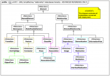
UML2 simplified key "relationship" metaclasses hierachy - ADVANCED REFERENCE ONLY This content has been marked as discussing an ADVANCED topic! Gallery Tutorial TRAIL: Webel's ultimate guide to Systems Modeling Language (v1) with MagicDraw/Cameo Section 01:02: UML 101 for model-based systems engineering with SysML Slide kind UML Profile Diagram
Dependency vs Usage vs Association vs Connector Gallery Tutorial TRAIL: Webel's ultimate guide to Systems Modeling Language (v1) with MagicDraw/Cameo Section 08:01: The building Blocks of SysML Slide kind SysML Block Definition Diagram (BDD)
When dealing with required Interfaces you must use Usage (not Dependency) and it has dedicated "socket" notation.
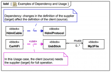
A Usage is a Dependency in which the client Element requires the supplier Element (or set of Elements) for its full implementation or operation. Source Unified Modeling Language 2.5.1
MagicDraw/Cameo: If you can't find Usage on a particular diagram just use a Dependency then the refactor context menu item.
Examples of Dependency and Usage Gallery Tutorial TRAIL: Webel's ultimate guide to Systems Modeling Language (v1) with MagicDraw/Cameo Section 08:01: The building Blocks of SysML Slide kind SysML Block Definition Diagram (BDD)
MagicDraw/Cameo 19SP3: Validation of required and provided Interfaces proxied between a ProxyPort and a part with a compatible contract fails
[HISTORICAL] UML-STYLE: Hybrid SUV example: Ports with required/provided Interfaces (Internal Definition Diagram) ARCHIVAL (2020): This content is now considered historical only! Gallery Tutorial TRAIL: Webel's ultimate guide to Systems Modeling Language (v1) with MagicDraw/Cameo Section 09:04: Ports and contracts Slide kind SysML Internal Block Diagram (IBD)
[HISTORICAL] UML-STYLE: Hybrid SUV example: Ports with required/provided Interfaces (Block Definition Diagram) ARCHIVAL (2020): This content is now considered historical only! Gallery Tutorial TRAIL: Webel's ultimate guide to Systems Modeling Language (v1) with MagicDraw/Cameo Section 09:04: Ports and contracts Slide kind SysML Block Definition Diagram (BDD)
SysML-1.6: Needs a constraint on ~InterfaceBlock making the implied inversion of provided/required Interfaces explicit
SysML directed features displayed on Port symbols are often far clearer than UML-style provided/required Interface "ball (lollipop) and socket" notation
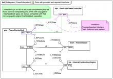
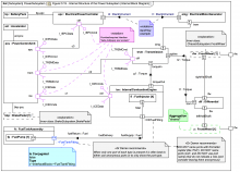
Figure D.19 - Internal Structure of the Power Subsystem (Internal Block Diagram) Gallery Tutorial TRAIL: The SysML-1.6 Hybrid SUV sample and specification diagrams in MagicDraw/Cameo (with annotations) [UNDERGOING UPDATE to SysML1.7] Section Section: SysML-1.6: HSUV sample Slide kind SysML Internal Block Diagram (IBD)
Dependency/Usage relationships in some referenced UML/SysML diagrams on this site are for educational illustration only, they are NOT part of the actual model.
A required Interface may be shown by the socket notation attached to the Port. Source Unified Modeling Language 2.5.1