
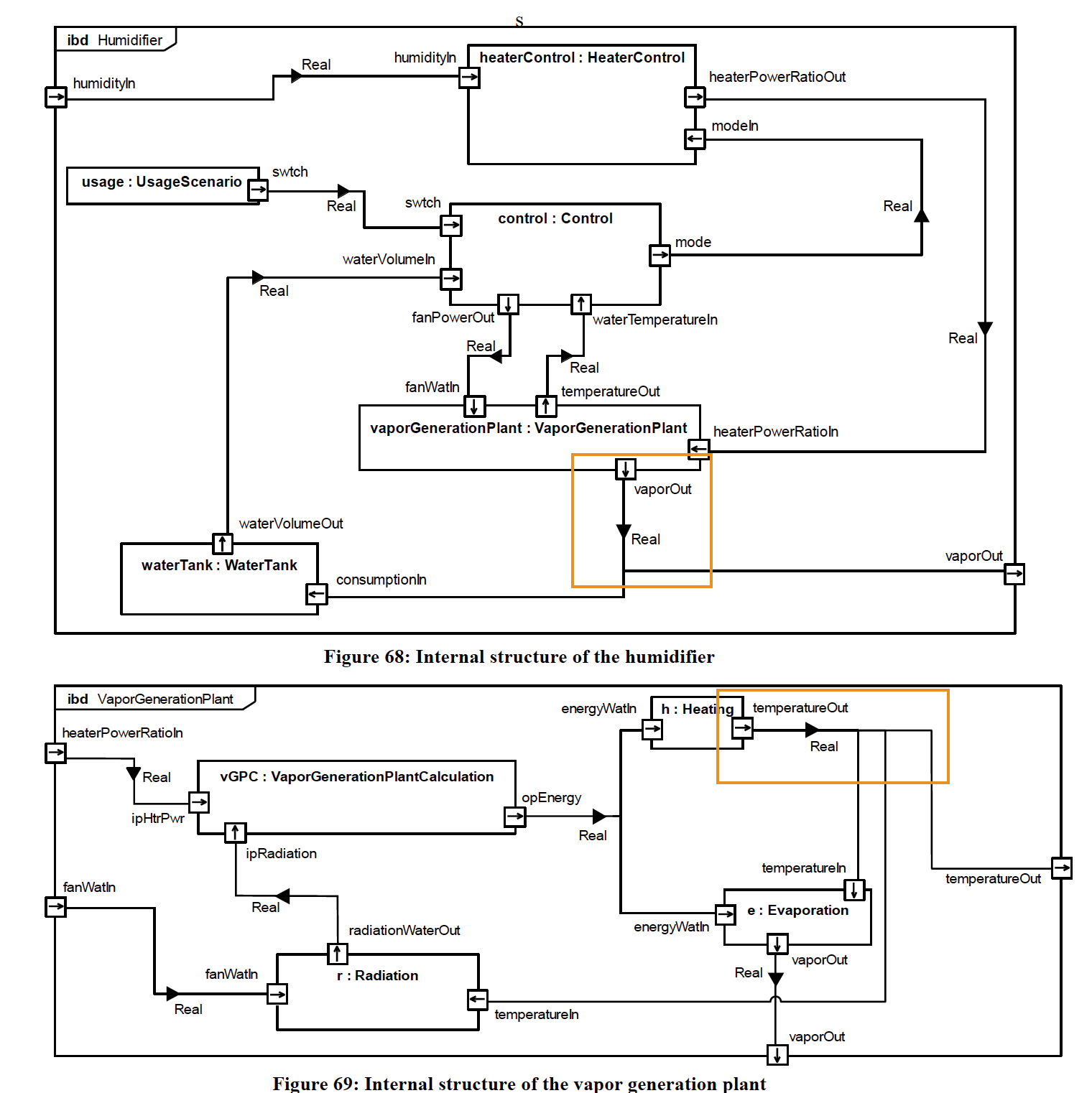
The image shows an annotated version of Figure 66 and Figure 67 from SysPhS-1.1.
In Modelica there is no explicit support for a "node". For electrical systems one can use an explicit Pin. See also: Is it possible to add a node to a circuit model in SystemModeler?
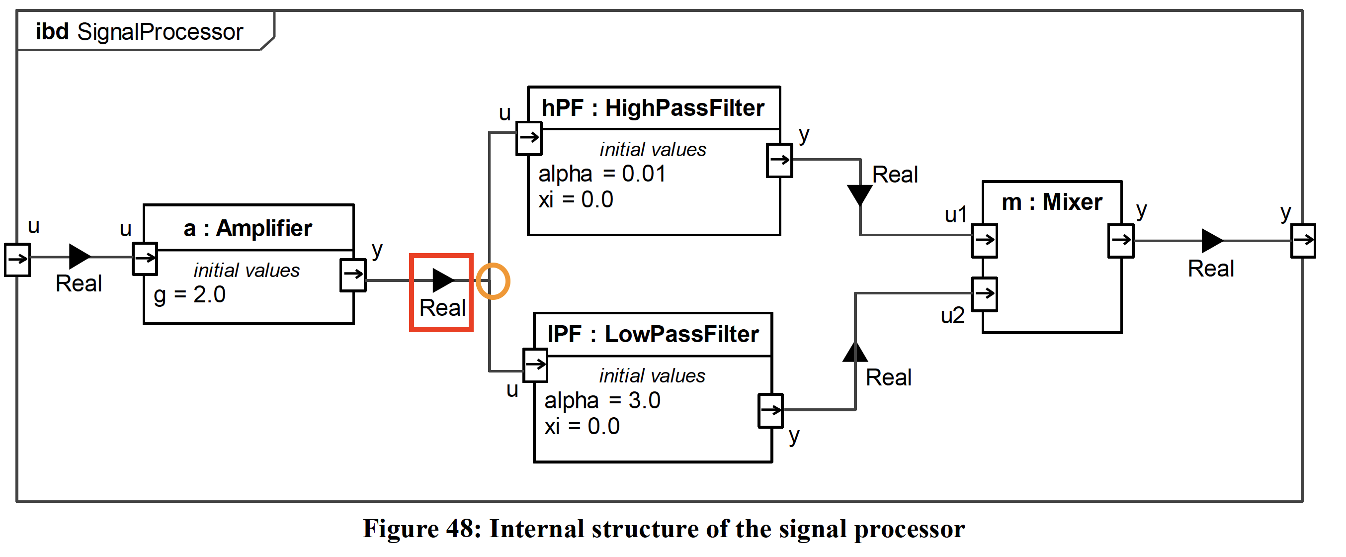
Having overlapping Connector symbols is against Webel Best Practice. It can be easily misunderstood as implying that signal values or physical flow values are summed (especially in the case of electric current, because it looks like wires connected at a node).
Sometimes this is a hint to use nested Ports to provide a distinct connection point with each target, although that approach does not "play nicely" with SysPhS-1.1 unless additional constraints are introduced.
At the very least, one can show distinct connection points by enlarging the Port symbol, and avoid having any overlapping portions of the Connector lines (crossing is fine).
There's another SysPhS electronics counter-example here: And here: Remember: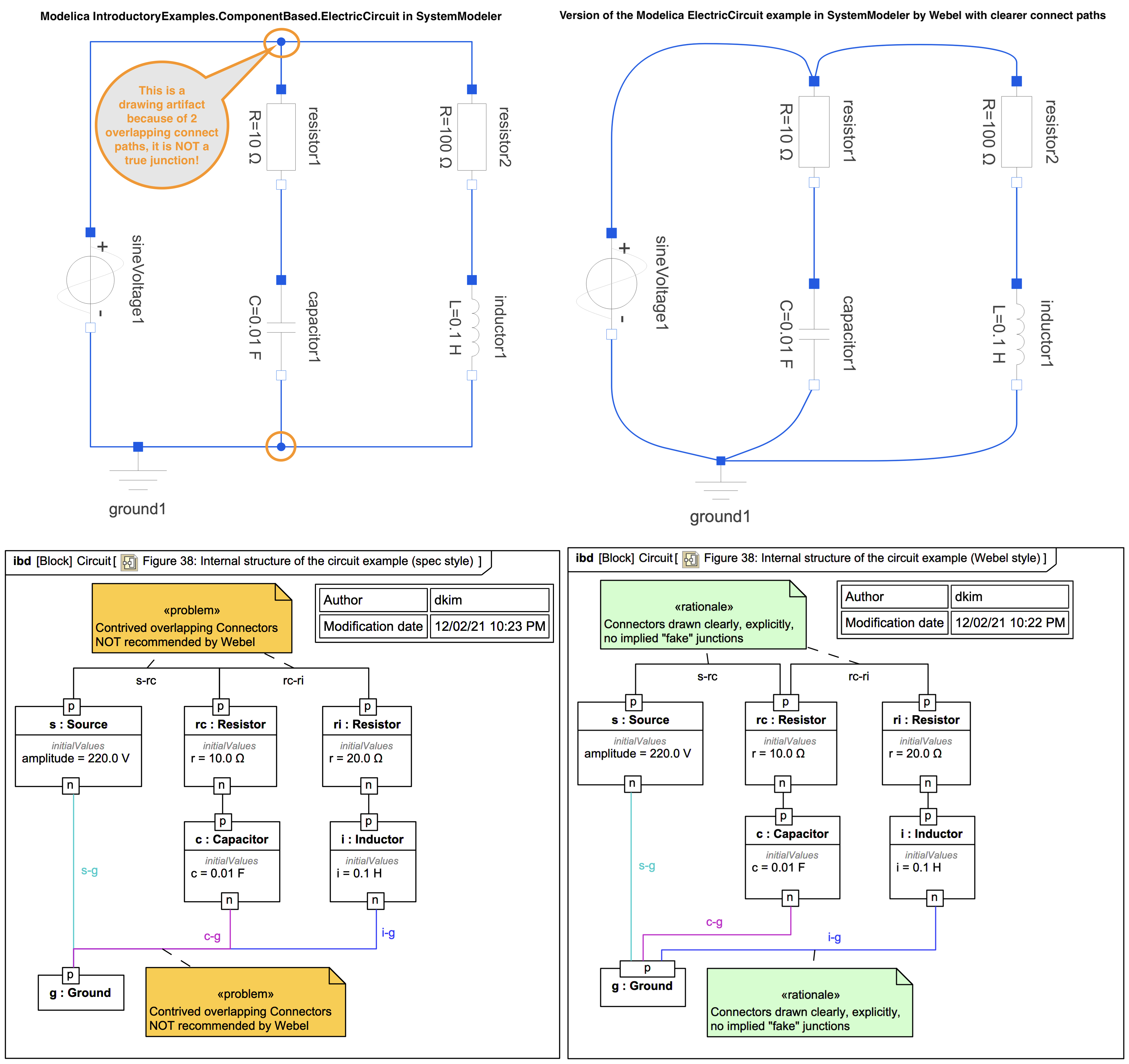
In Modelica there is no explicit support for a "node". For electrical systems one can use an explicit Pin. See also: Is it possible to add a node to a circuit model in SystemModeler?