
This page shows (for purposes of historical reference only) an OBSOLETE early attempt at re-appropriating Unified Modeling Language (UML®) for port-based systems engineering. Please see now instead for latest Systems Modeling Language v1 (SysML®) !
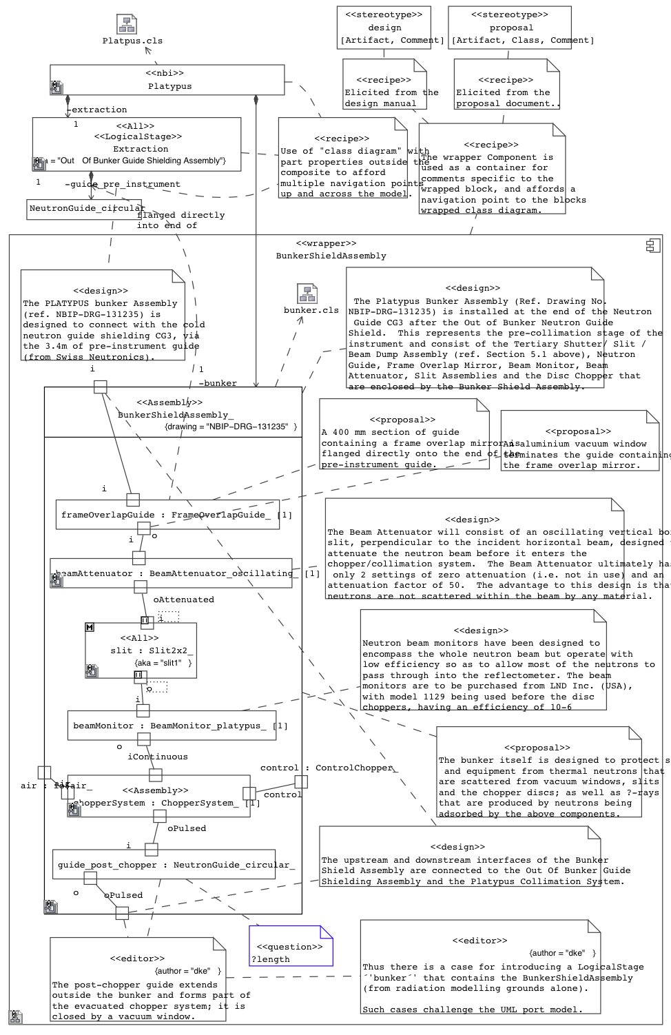
The «block» class is wrapped by a block «wrapper» Component that is hyperlinked to a block wrapper class diagram for the block. Other «block» classes are shown to provide a usage context and alternative navigation points[fn]Since 2008 MagicDraw UML supports easier navigation to clients of a Class in a Composite Structure Diagram, so there is less need for this strategy now. Note also that it is not always wise to indicate the usage context explicitly, it can prevent modularisation ![/fn]. Physical values (part-specific defaults) are not easily shown on the parts[fn]Since 2008 MagicDraw UML supports SysML-style property-specific value indicators on UML Property symbols in composite structure diagrams[/fn]. The limits of the port-based modelling and assembly interpretations are challenged by a postbunker guide that is part inside and part outside the bunker.
Note that this notation precedes the introduction of the early Systems Modeling Language v1 (SysML®) "FlowPort" (which is now achieved since SysML1.4 using FlowProperties on Block).
Such "binding" of text to Unified Modeling Language (UML®) and Systems Modeling Language v1 (SysML®) models for elicitation of model elements has since been formalised by Dr Darren as the Webel Parsing Analysis recipe.