Tags and keywords
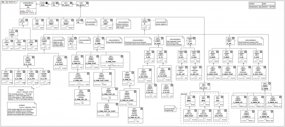
All types of all pins on all headers on an Arduino Mega2560R3, named according to overloaded functionality.
This diagram is at the limit of what should be included in a single Package Diagram, and an a real project could perhaps be split up according to functionality groups. (It's included here all-in-one just for the convenience of this trail.)
The names and custom stereotypes indicate the various technologies. Note that the application of a stereotype here just means that the element "has something to do" with that technology. It provides, amongst other things, a way to easily identify and search for elements that are part of a technology layer. Physical packaging can't be used for that here, because some Pins are involved with more than one technology!
This is not a tutorial on each technology or each function of an Arduino, a brief description only is given here:
«power»: Involves power (voltage input, regulated voltage bus, or output).
«control»: Involves control such as for 'RESET'.
«ref»: Acts as a voltage reference. Ground (name 'GND') is classified as «ref» but packaged with other power elements (if you look at the board the ground header pins are mostly organised amongst or near the power-related header pins.
«digital»: Most header pins serve as general digital i/o, indicated by 'D' in the name.
«analog»: Means a pin has something to do with the analog domain. Some header pins also serve as analog-to-digital converters, indicated in the name by 'A' (short here for ADC).
«comparator»: Involves the analog comparator. Strangely, although larger than other boards, the Mega only has the AIN1 (not also the AIN0) connected to the Atmel Mega pins.
«timing»: Involves timing, timers ('T' in name), counters ('OC' in name).
«PWM»: Involves Pulse Width Modulation, indicated in the name by 'PWM'. Some of the Mega PWM pins have a higher default frequency marked with 'FAST'.
«JTAG»: Involves the Joint Test Action Group testing protocol.
«interrupt»: Involves interrupts. There are two versions, "hardware" (name 'INT') and "software" (name 'PCINT').
«UART»: Involves the Universal Asynchronous Receiver-Transmitter serial communication protocol, where 'RX' is receive and 'TX' is transmit.
«I2C»: Involves the Inter-Integrated Circuit (I2C) synchronous serial communication protocol
«SPI»: Involves the Serial Peripheral Interface (SPI) synchronous communication protocol. This also includes pins for the 2 separate 3x2 headers for In-Circuit Serial Programming of the ATmega16u2 and ATmega2560 chips respectively.
«XMEM»: Involves extended (off board) memory.
Note how most of these «pin» blocks also have stereotyped Ports (in fact typed by InterfaceBlocks). These indicate the logical contracts (in Arduino usually determined at runtime via software library commands), as opposed to the physical pin connection contract (in this case 0.1" female header pins). Note how more than one logical contract can be inherited, because some pins have more than one logical function.


