SysML/UML: MagicDraw/Cameo: To display the body of an OpaqueBehavior on a usage (CallBehaviorAction) in an Activity Diagram use an element property callout of 'Body' into a Note with a handle to the CallBehaviorAction
MagicDraw/Cameo 19SP3: The property path in callout does always correspond to the SysML spec examples.
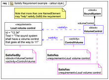
Satisfying Requirements and the Satisfy relationship Gallery Tutorial TRAIL: Webel's ultimate guide to Systems Modeling Language (v1) with MagicDraw/Cameo Section 16:01: Requirements engineering in SysML Slide kind SysML Requirement Diagram
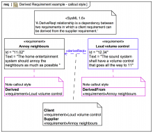
Derived requirements and the DeriveReqt relationship Gallery Tutorial TRAIL: Webel's ultimate guide to Systems Modeling Language (v1) with MagicDraw/Cameo Section 16:01: Requirements engineering in SysML Slide kind SysML Requirement Diagram
The Verify relationship is shown on Figure 16-7 using callout notation anchored to the diagram frame, which indicates that the BurnishTest test case verifies the Burnish requirement. Source OMG Systems Modeling Language (SysML) 1.6
Figure 17-1 [Figure 16-7] is a state machine diagram of the BurnishTest test case, which expresses the textual sequence and criteria of the Burnish requirement in state machine form. Source OMG Systems Modeling Language (SysML) 1.6
The Burnish requirement is shown as having a Verify relationship to the BurnishTest test case using callout notation on the diagram, indicating that the Burnish requirement is verified by the BurnishTest test case. Source OMG Systems Modeling Language (SysML) 1.6
MagicDraw/Cameo: To callout the element properties of Diagram's context Element into a Note in that Diagram use the context menu item Represent Diagram Context on the Note!
SysML-1.6: double-callout into one Note from 2 part Property symbols in 'Figure 16.4: Requirement satisfaction in an internal block diagram' is not tool friendly
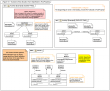
Figure 15-7: Example of flow allocation from ObjectNode to FlowProperty Gallery Tutorial TRAIL: The SysML-1.6 Hybrid SUV sample and specification diagrams in MagicDraw/Cameo (with annotations) [UNDERGOING UPDATE to SysML1.7] Section Section: SysML-1.6 specification diagrams: 15 Allocations Slide kind hybrid diagram SysML Activity Diagram SysML Internal Block Diagram (IBD)
MagicDraw/Cameo does not seem to offer the display option Apply SysML Callout Style on CentralBufferNode
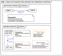
Figure 15-6: Example of flow allocation from ObjectFlow to ItemFlow Gallery Tutorial TRAIL: The SysML-1.6 Hybrid SUV sample and specification diagrams in MagicDraw/Cameo (with annotations) [UNDERGOING UPDATE to SysML1.7] Section Section: SysML-1.6 specification diagrams: 15 Allocations Slide kind hybrid diagram SysML Activity Diagram SysML Internal Block Diagram (IBD)
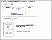
Figure 15-5: Example of flow allocation from ObjectFlow to Connector Gallery Tutorial TRAIL: The SysML-1.6 Hybrid SUV sample and specification diagrams in MagicDraw/Cameo (with annotations) [UNDERGOING UPDATE to SysML1.7] Section Section: SysML-1.6 specification diagrams: 15 Allocations Slide kind hybrid diagram SysML Activity Diagram SysML Internal Block Diagram (IBD)
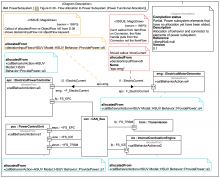
Figure D.39 - Flow Allocation to Power Subsystem (Power Functional Allocation) Gallery Tutorial TRAIL: The SysML-1.6 Hybrid SUV sample and specification diagrams in MagicDraw/Cameo (with annotations) [UNDERGOING UPDATE to SysML1.7] Section Section: SysML-1.6: HSUV sample Slide kind SysML Internal Block Diagram (IBD)
MagicDraw/Cameo: 19SP3: Callout of allocatedFrom on Connector vs ObjectFlow shows «decisionInputFlow» not «objectFlow» keyword
MagicDraw/Cameo 19SP3: Can't callout from ItemFlow on Connector, the Note handle pulls from the Connector not the ItemFlow
MagicDraw/Cameo: The display option Apply SysML Callout Style shows elements with their Metaclass or Stereotype keywords and no vendor-specific icons