
Tags and keywords
CAUTION: The usage of the term Pin here has nothing to do with the UML/SysML Pin on an Action in an Activity Diagram!
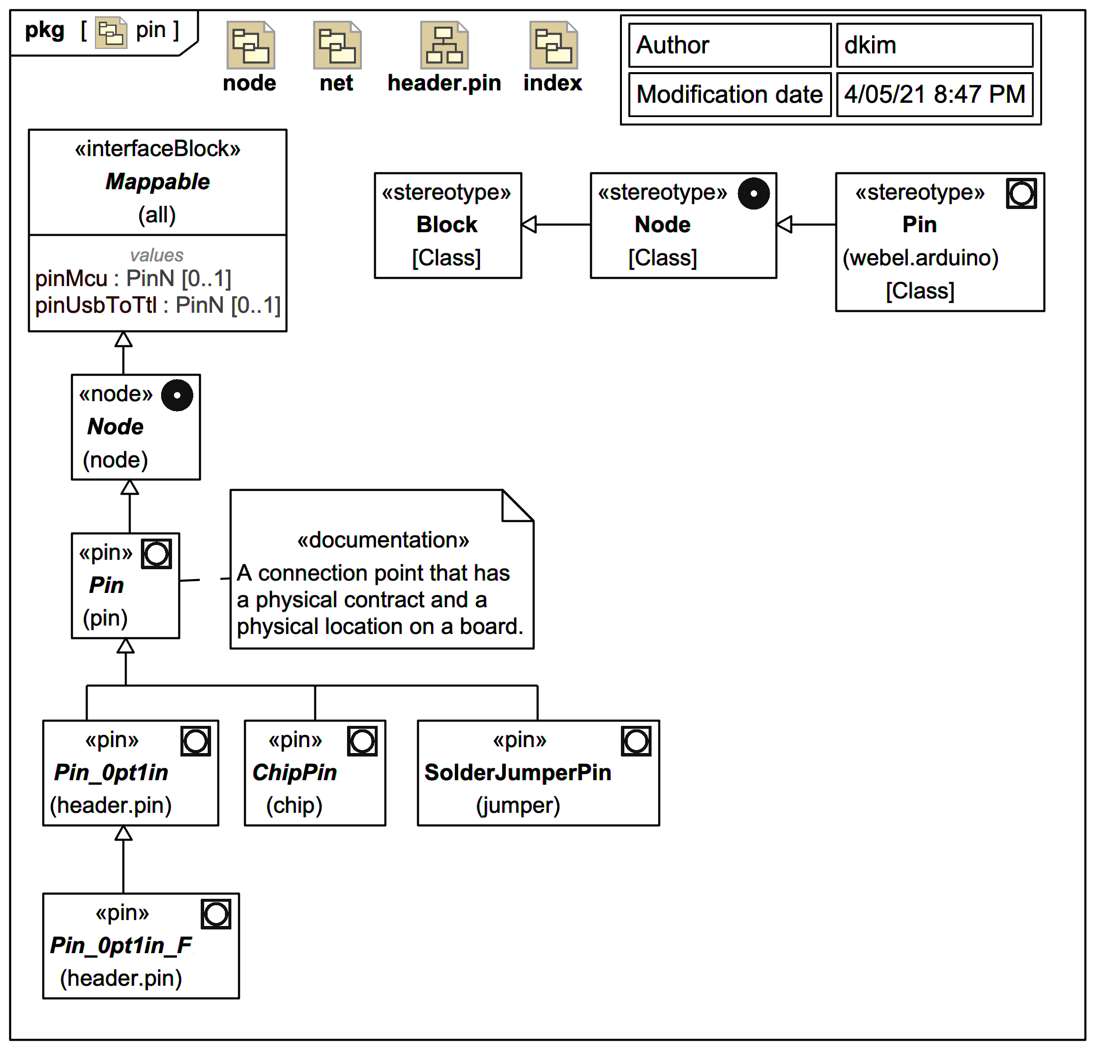
The two kinds of pins we'll be dealing with most on the Arduino Mega 2560 are:
Pin_0pt1in_F: Female header pin with 0.1" pitch.ChipPin: Pin on an IC. More specifically, the physical connection point of a surface mounted IC is typically a small solder pad, but we won't have to deal with the distinction in this trail.
A Pin has a physical connection contract and a location on a board. For example, to plug into a 0.1" female header pin you need to use a matching 0.1" male jumper cable or similar.
Note again that more specific Pin types may carry one or more Ports typed by InterfaceBlocks as logical contracts encapsulating the various functionalities that a single Pin may offer (determined in the case of Arduino often by a combination of specific wiring and patch library commands).
Mostly, however, in this trail, we'll just be modelling the standard board connections at the physical level, not a specific application of the board.